Particle Tracking
Introduction
Several methods have been developed to obtain trajectories of moving organisms. Among these methods, three-dimensional particle tracking velocimetry offers the advantage that it allows fully automatic processing of long sequences of stereoscopic images from which the position of a large number of particles and their trajectories in the three-dimensional space can be automatically recovered. The technique was originally developed to measure velocity and velocity gradients along tracer trajectories in turbulent flows (Maas et al. 1993; Malik et al. 1993; Lüthi 2002) and we have recently applied it to study the swimming behavior of zooplankton. This measurement technique identifies and follows individual tracer particles in time and provides a Lagrangian description of their displacements in the three-dimensional space. The calibration of the stereo rig allows the reconstruction of the object space geometry and the determination of the particle coordinates. The reconstruction of particle trajectories is done by establishing spatio-temporal correspondences between particle positions in consecutive frames.

Pinhole camera model
This method is based on the pinhole camera model, which is an approximation of the relationship between a point Mw in the world reference frame and its projection Mi onto the focal plane of the camera and finally onto the point Mp in the final image. In this model, the coordinates of Mw and Mp are related by a set of extrinsic and intrinsic camera parameters. Extrinsic parameters define the location and orientation of the camera reference frame with respect to the known world reference frame, and are represented by the translation vector between the relative positions of the two frames and the rotation matrix which brings the corresponding axes into alignment. Intrinsic camera parameters are required to link the point Mw expressed in the camera reference frame with the coordinates of its corresponding point Mp. A perspective projection links the coordinates of Mw to the point Mi in the image plane. A second transformation describes the sampling of the focal plane by the camera sensor and links the coordinates of Mi to the coordinates of Mp. The combination of these three transformations gives the collinearity equations. The basic pinhole model is then extended with some corrections for radial and tangential distortions. The camera model becomes non-linear and can be expressed as a vectorial function which is suited to be linearized as observation equations. Finally a radial shift is calculated and added into the collinearity equations to compensate for the influence of the multimedia geometry (Maas et al. 1993).
Epipolar geometry
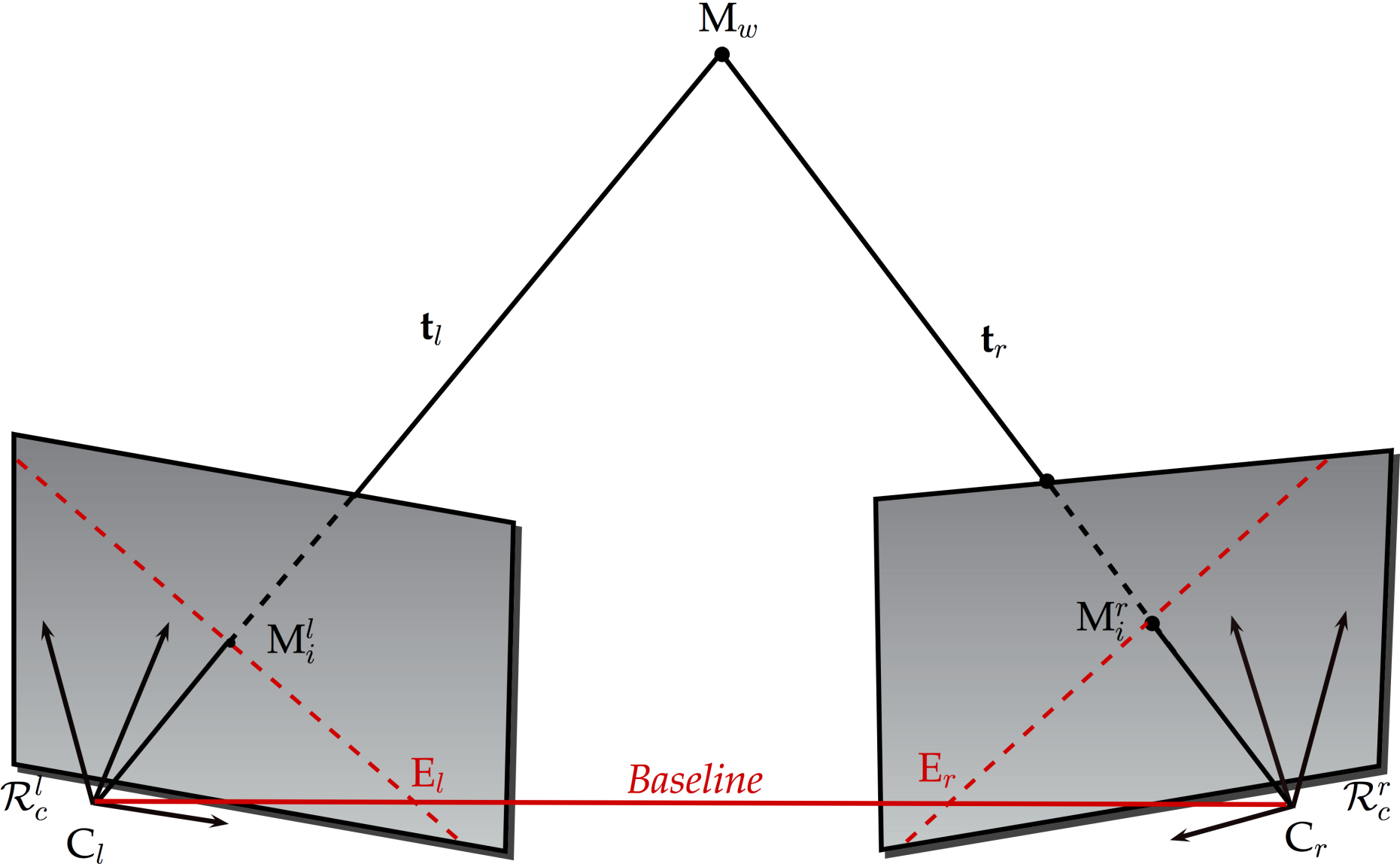
The extended pinhole model is being applied for a spatial resection using control points with known coordinates and introducing the parameters of exterior and interior orientation, lens distortion and sensor distortion as unknowns (Maas et al., 1993). Knowing the camera orientation and parameters, it is then possible to establish correspondences between particle image coordinates. A point in the world reference frame is projected onto both image planes to points constituting a conjugate pair. For a point in the left image plane, its conjugate in the right image plane lies on a line called the epipolar line. An essential matrix expresses the relation between these two points. Given a point in one image plane, multiplying its coordinates by the essential matrix will determine which epipolar line to search along in the second image plane. After corresponding particles on the two images are found, the three-dimensional coordinates are derived by forward intersection, introducing their coordinates as unknowns in the augmented projection model (Papantoniou and Dracos 1989; Maas et al. 1993; Malik et al. 1993; Dold and Maas 1994).
Particle tracking
Particles are detected within images by the application of a peak-fitting routine after high-pass filtering, and their center of gravity is calculated with a weighted gray value operator (Maas et al. 1993). The corresponding particle coordinates in the object space form the point clouds at each time instant before the tracking is performed (Willneff, 2003). The tracking procedure then selects correct links for the individual particle from one time step to the next, using the information extracted from both image and object spaces (Dracos 1996; Willneff 2003). If a particle can be tracked in the object space over several consecutive time steps, its position in the next time step can be predicted assuming constant velocity or constant acceleration and back-projected onto the images of all cameras. The search in the image space after projection of the search volume from the object space either confirms the predicted location or leads to unmatched detections.
Open-source particle tracking velocimetry
The external pageOpenPTV foundation is a collaborative effort of several research groups that develop better software for 3D-PTV. OpenPTV is based on the core algorithms developed at ETH Zurich. The branches of the original code have been developed independently by the group Turbulence and Vortex Dynamics at TU Eindhoven and by the Turbulence Structure Laboratory at Tel-Aviv University.
References
- Dold J., Maas H.G. (1994) An application of epipolar line intersection in a hybrid close range photogrammetric system. IAPRS Vol. 30, Part V, ISPRS Com. V Symposium, Melbourne, Australia.
- Dracos T. (Ed.) (1996) Three-dimensional velocity and vorticity measuring and image analysis techniques: Lecture notes from the short course held in Zürich, Switzerland, September 1996. ERCOFTAC Series, Vol. 4. Springer Netherlands.
- Lüthi B. (2002) Some aspects of strain, vorticity and material element dynamics as measured with 3D particle tracking velocimetry in a turbulent flow. Doctoral Thesis, ETH Zurich.
- Maas H.G., Gruen A., Papantoniou D. (1993) Particle tracking velocimetry in three-dimensional flows. Part I. Photogrammetric determination of particle coordinates. Exp. Fluids 15:133-146.
- Malik N.A., Dracos T., Papantoniou D. (1993) Particle tracking velocimetry in three-dimensional flows. Part II: Particle tracking. Exp. Fluids 15:279-294.
- Papantoniou D., Dracos T. (1989) Analyzing 3-dimensional turbulent motions in open channel flow by use of stereoscopy and particle tracking. In: Hernholz, Fiedler(Ed.), Advances in Turbulence 2. Springer Verlag, Heidelberg, Berlin, pp. 278-285.
- Willneff J. (2003) A spatio-temporal matching algorithm for 3D particle tracking velocimetry. Doctoral Thesis, ETH Zurich